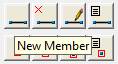
Click on New Member.
Click on origin joint.
Click on terminal joint.
Member Property panel becomes visible.
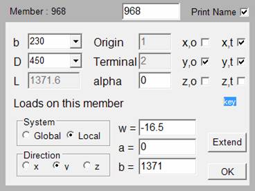
Select width ‘b’ of the member.
Select depth ‘D’ of the member.
‘l’ is the length of the member
origin is the origin joint you selected.
Terminal is the terminal joint you selected.
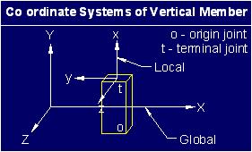
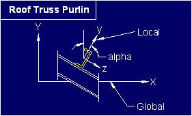
‘alfa’ is the rotation of the member about its x-axis i.e. longitudinal axis. For a beam In building frames you would keep it as zero. The alfa is measured in radians. You can change it to change the orientation of columns. The local co-ordinate system of a vertical member with alfa equal to zero is shown below. Shown below is a roof truss purlin with rotated x-axis.
x,o is the rotational degree of freedom about x-axis at the origin joint. x,t is the rotational degree of freedom about x-axis at the terminal joint.
y,o is the rotational degree of freedom about y-axis at the origin joint. y,t is the rotational degree of freedom about y-axis at the terminal joint.
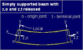
z,o is the rotational degree of freedom about z-axis at the origin joint. z,t is the rotational degree of freedom about z-axis at the terminal joint.
This Member Property panel shows typical selection of degrees of freedom for a simply supported beam.
If you want the member not to resist tortional moment then you must release only one of the x,o and x,t. If both ends of a member are allowed to rotate about x-axis then it will become unstable member.
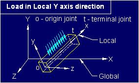
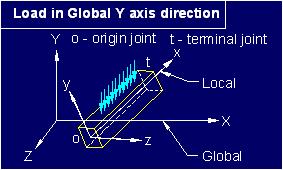
Following figures show rotation due to loads in y-axis and z-axis direction.
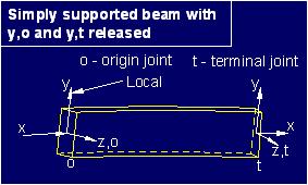
In building frames the beams will normally not have load in the local z-axis direction so you do not have to release y,o and y,t.
If you want a beam not to resist moment about z-axis which is due to load in y-axis you release z,o and/or z,t.
Please go through example projects for member connectivity.
Following figures show loads in local y-axis co-ordinate direction and global y-axis co-ordinate direction.
w’ is the self weight or initial uniformly distributed load UDL
‘a’ and ‘b’ are distances from origin joint as shown below.
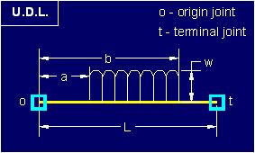
The application places a=0 and b=l which means that the load is on the entire length of the member.
If the default value for self weight is set then it is placed in front of ‘w’ by the application.
Click ‘Extend’ if you want the next member’s origin joint as the terminal joint of this member and then the terminal joint of the next member.
Click ‘Ok’ to finalize this member