akses is a structural analysis and design software developed especially for Indian structural engineers. It is a finite element based analysis software which is developed specifically for design of reinforced concrete buildings. The software is developed by practicing structural engineers with emphasis on traditional Indian practice of site drawings. Once the design is completed, the site drawings are created in .dxf format which can be opened in various CAD softwares such as AutoCAD. In order to minimize data entry time geometric coordinates can be directly imported from the architectural working drawings.
Modeling –
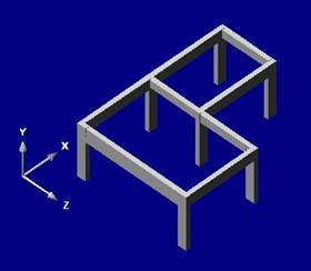
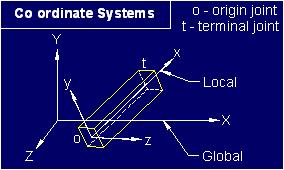
Global Coordinate System
Two reference coordinate systems are used while modeling the building space frames. The global coordinate system is used to define the shape of the building space frame. X–Z plane of the global coordinate system is where the floor plan of the building is drawn. Y axis of the global coordinate system is in the direction of the height of the building. The other view is an isometric view. The local coordinate system is used to define loads and forces of the members. X–axis of the local coordinate passes through the longitudinal axis of that member.
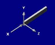
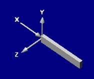
Local Coordinate System
Both the coordinate systems are graphically described here.

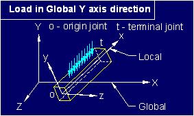
The loads can be applied in local or global direction. If you want to apply loads in any other direction, you can resolve them in to a co-ordinate system and apply the resolved loads in that co-ordinate system.
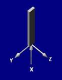
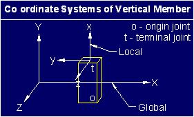
The rotation of a member about its x-axis is defined by angle alpha. Following figure shows a roof truss purlin with alpha. If you create a new vertical member without specifying alpha then its local co-ordinate system will be as shown below.
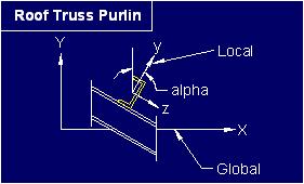
You can change the orientation of column by changing its alpha. Since the finite element method uses stiffness of members to determine the deflections and forces in the structure it is vary important that you specify correct dimension and orientation of the cross section of members.
As it can be
seen from the figures, in normal cases the dead load and live load acting on a
beam member would be in the negative Y direction of the local coordinate system.
Horizontal loads acting on the whole structure would be in the X or Z direction
of the global coordinate system.
In order to generate the geometry of a space frame one has to first define nodes
or joints. Nodes / Joints are locations in the global coordinate system and are
defined using three coordinates namely x, y and z coordinate of the global
coordinate system. Members of the space frame are then defined with reference to
these nodes. Nodes / Joints are also used to define supports of the space frame
and nodal loads in the global coordinate system.
Degrees of freedom -
All members have 6 degrees of freedom at each end. It means that a member ends can freely displace in 3 direction and can freely rotate about 3 axis. While modeling a space frame all these degrees of freedom must be decided before performing the structural analysis.
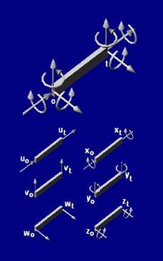
12 degrees of freedom
o – origin node, t – terminal node
u – displacement in x direction , v – displacement in y direction, w –
displacement in z direction
x – rotation about x axis, y – rotation about y axis, z – rotation about z axis
These degrees of freedom are defined either as restrained [R] or free [F]. If a
beam member is simply supported on both ends then its rotational degree of
freedom at origin as well as terminal node would be free [F]. When load is
applied in Y direction it would rotate about Z axis at the origin node and at
the terminal node.
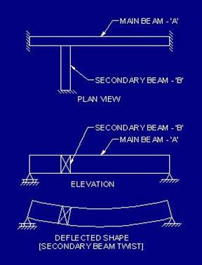
Effect of rotational stiffness of a secondary beam on the main beam.
A simply supported beam ‘A’ with a secondary beam ‘B’ resting on it is shown in Fig-1.4. It can be seen that when the load is applied on the structure, the main beam will deflect and it will twist the secondary beam. If the secondary beam is rigid in torsional stiffness then it will resist the deflection of the main beam and the bending moment and shear force in the main beam will be affected by the torsional stiffness of the secondary beam. In reinforced concrete structures the secondary bean can be designed to have negligible torsional stiffness simply by not providing torsional reinforcement. When the secondary beam is not designed to resist torsional moment, there will be negligible torsional stiffness in the secondary beam and it will not affect the deflected shape of the main beam. While modeling this structure rotational degree of freedom of the secondary beam at the connecting node should be defined as free [F].
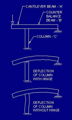
Effect of deflection of beam on column
A cantilever beam ‘A’ and a counter balance beam ‘B’ resting on a column ‘C’ is shown in Fig-1.5. When load is applied on beam ‘A’ the deflection of beam ‘A’ will introduce deflection in beam ‘B’ and column ‘C’ as shown in figure with column without hinge. If the column is designed to have negligible bending stiffness then the structure will behave as if there is a hinge in column as shown in Fig-1.5. While modeling this structure, appropriate rotational degree of freedom of the column member at the connecting node should be defined as free [F] so that moment is not introduced in the column. In reinforced concrete structures the connections between members can be easily designed to be rigid or hinged.
Loads -
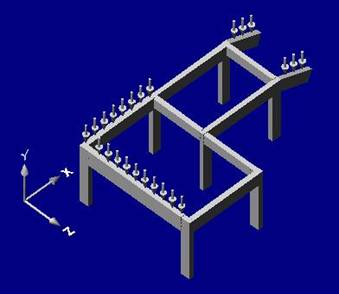
Loads acting on a building frame
Imposed loads
and self weight of the structure act in the direction of gravitational force. As
discussed previously, the direction of these loads is in the negative Y axis
direction of the global coordinate system.
Figures show loads in negative Y direction of the global coordinate system. Note
that for horizontal beams, the direction of load is in negative Y direction of
the global as well as local coordinate system. For inclined beams, the direction
of loads is in global coordinate system but it is not in the direction of local
coordinate system. In the case of loads on inclined beams, the loads should be
applied in the global coordinate system and the software resolves these forces
in the local coordinate system and then computes the member end forces.
In case of beams supported at both ends, since the direction of Y axis of local as well as global coordinate system is the same, loads should be applied in the local coordinate system so that the software does not have to spend time in resolving the forced in the local coordinate system.
Supports –
It is discussed earlier that each member has 6 degrees of freedom at each node.
Similarly a support of the structure has 6 degrees of freedom. It means that a
support can displace freely along three axis of the global coordinate system and
it can freely rotate about three axis of the global coordinate system. Usually
all 6 degrees of freedom of a support is defined as restrained [R]. Some times
when hinges are provided at a support then corresponding rotational degree of
freedom is defined as free [F].
Since Reinforced concrete design part uses SI Unit system, length should be
defined in millimeters and force should be defined in Newton.
Please go through the sample projects and study how the member end restrains are specified in case of cantilever beams and column supporting them. In sample projects you will find cantilever beams, simply supported beams, grid beams and other types of member. You must always pay attention to the torsional degree of freedom of members connected in the same joint. The torsional stiffness of one member can provide moment resistance to other members.
If you want to have the diaphragm effect of slab on the structure you can use dummy beam members in the diagonal direction of the slab with large cross sectional area and rotational degree of freedoms set to unrestrained.
Tutorial -
Study architectural drawing given in DWG format file by the architect.

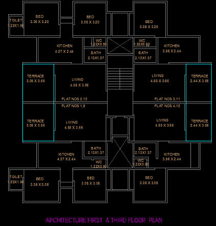
Decide beam and column locations.
Draw beam and column layout of each floor in the given DWG format file and get it approved from the architect.

Create a new layer named 'akses' in DWG format file.
Set current layer to 'akses'.

Scale should be 1 mm = 1 unit.

Draw LINES at the centerline of all beams. (Use only one floor plan.)
These LINES can be imported in to akses as members.

Save DWG file in DXF format. e.g. Demo3.DXF.

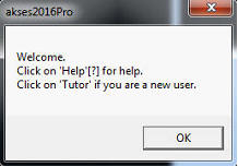
akses window will open.

Click on Login.
Following message will be visible.


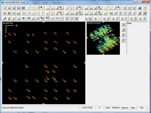
Imported Members will be visible.
Y coordinate of these members will be zero.

Enter Y distance.


Enter your values for the offset distance. You can use positive or negative values.
The application will create a new joint at the offset distance.
![]()
The application writes the current level of the plan view in this field of the Status Bar.
Left click and right click is used to change the level of the plan view.
Use left click to view upper level or right click to view lower level.
![]()

Follow this procedure to create all support joints.


![]()


Select 'b', the default width for members
Select 'D', the default depth for members
The application will provide these values when you define a new member.

Columns will be created from all support joints towards uppermost level.
![]()

![]()
Use left click to view upper.
![]()
![]()
![]()

![]()


All members at current level will be numbered / renumbered in a sequential pattern like B1, B2, B3, . . . .

![]()


Using this procedure remove member labels of all beams with multiple elements.

All members with member labels at current level will be renumbered in a sequential pattern like B1, B2, B3, . . . .


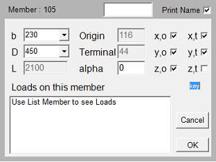
Click on Member which is on the left side of B8 in Plan View.
Member edit panel will become visible.

Press X key on your keyboard.
Member end restrains will change accordingly.
Member edit panel will become visible.

Press C key on your keyboard.
Member end restrains will change accordingly.
Click on Member which is on the right side of B8 in Plan View.
Member edit panel will become visible.
Press V key on your keyboard.
Member end restrains will change accordingly.
Note color code of B8 in the Plan and Isometric View.

Follow this procedure for rest of the beams with multiple elements.
Use Zoom Window / Zoom All buttons OR Mouse Wheel to zoom in and out the views.


Use Zoom Window / Zoom All buttons OR Mouse Wheel to zoom in and out the views.


![]()
Use left click to view upper level.

![]()

Columns will be created from all support joints towards uppermost level.


Multiple members can be deleted using select window.
Press left mouse button and drag mouse to select multiple members.


Multiple joints can be deleted using select window.
Press left mouse button and drag mouse to select multiple joints.


Enter your values for the offset distance. Use positive values.
The application will create a new joint at the offset distance.
![]()
Off member Number and on Joint Number.

Click on terminal joint.

Off joint Number and on member number
![]()
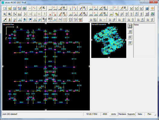
Below Fig. All Complete First Slab Level Framing


All members with member labels at current level will be renumbered in a sequential pattern like B1, B2, B3, . . . .


The application places values of long and short span from the space frame.
Select bar diameter, spacing and steel grade for short span.

![]()
![]()
Slab will be visible in the plan view.


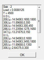
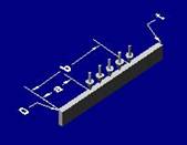
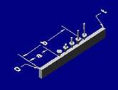
'#' represents member number.
'l' / 'g' represents local / global co-ordinate system.
'x' / 'y' / 'z' represents axis of direction of load.
'w' represents intensity of Uniformly Distributed Load.
'a' represents distance form origin joint.
'b' represents distance form origin joint.
Follow this procedure to create all other slabs.


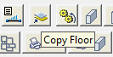
Use copy floor command to copy all these joints, members, slabs and loads at upper level.


Left Click on Level.
![]()
Upper level will be visible in the plan view.

Follow this procedure and create all required levels of slabs / beams.
Sort joints in vertical Y direction.

Columns will be created from all support joints towards uppermost level.

![]()
![]()


To rotate all columns Hold Ctrl command and Click on Edit member.
It shows message to enter Alfa value (value should be in radian).
To select particular column Hold Alt command and Click on Edit member.
It shows message to select particular column.
select particular column and enter Alfa value (value should be in radian).


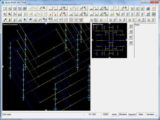
Column will be Rotated, it can view at the top left corner of plan view.

Columns will be Rotated, it can view at plan view.

![]()
![]()

![]()
![]()
Larger view will show isometric image.

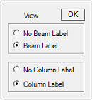
Right click on members.
window panel will appear like above.
Select no beam label, select column label as shown above.
Click ok.


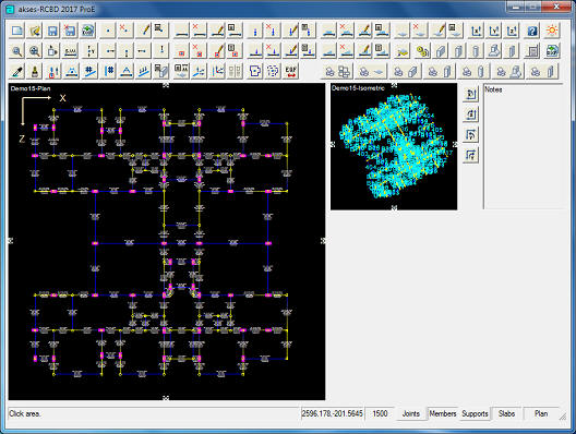
Click on the isometric view to select first corner of zoom window.
Click on the isometric view to select the other corner of zoom window.

![]()
All columns will be numbered / renumbered in a sequential pattern like C1, C2, C3, . . . .
It is desirable to sort joints in Y direction before using this command.

![]()
Larger view will show Plan image.


All members at current level will be numbered / renumbered in a sequential pattern like B1, B2, B3, . . . .

Change column restrains if required.


The analysis takes few minutes depending on the size of the structure.
Following message will be visible when analysis is done.

![]()
![]()
Slabs will be invisible in the plan view.


Beam section properties will become visible.


Schedule of designed Beams will become visible.


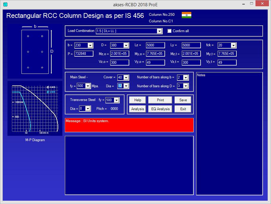
The application places value of length of column member in front of lz and ly.
Select steel grade and bar arrangement for main steel for the first trial.
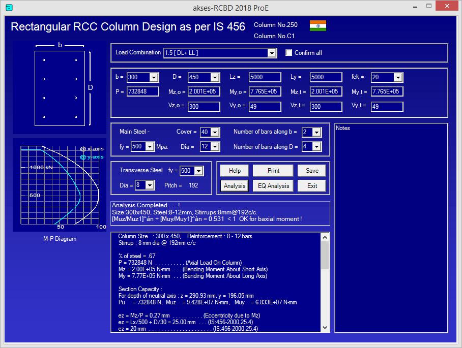


Schedule of designed Columns will become visible.


The application also places column section details of selected column if it is designed.
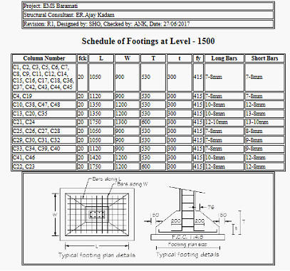
Select desired values of 'B' and 'D' i.e. width and depth of the footing at the top.
Select desired values of 'W' and 'L' i.e. width and length of the footing at the bottom.
Select desired values of 'T' and 't' i.e. maximum and minimum height of the footing.

When the capacity of the footing is satisfactory click Save.
Dowels may be needed if fck of column is higher than fck of footing.

Schedule of designed footings will become visible.

Enter desired scale for key plans.

Enter desired name for output file.

DXF format file will be created which will have following details in it.
Key Plans at all levels.
Schedule of Slabs at all levels.
Schedule of Beams at all levels.
Schedule of Columns at all levels.
Schedule of Footings.
Typical Beam section.
Typical Column / Footing section.
Typical Staircase sections.
Name Plate.
You can open DXF format file in AutoCAD or similar software and plot the results.

End of Document.